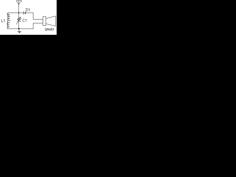
I have received a number of emails regarding schematics for crystal radios. After about the third email, I figured that I may as well put one on my page. So here it is. The circuit is very simple with only 5 parts, but performs very nicely when used with the right size antenna.

| C1 | 1 | Tuning Capacitor (See Notes) | |
| D1 | 1 | 1N34 Germanium Diode | |
| L1 | 1 | Loopstick Antenna (See Notes) | |
| SPKR1 | 1 | Crystal Earphone | |
| MISC | 1 | Wire, Board, Wire For Antenna, Knob For C1 |
1. C1 and L1 can be bought, or salvaged from an old AM radio (which is where I got mine). You may need to experiment with the connections on L1 in order to get the best (or any) signal.
2. You may or may not need the ground connection. I never use it and the radio usually works fine without it.
3. The bigger the antenna, the more stations you pick up and the louder you hear them. On my radio, I get about 10 stations, 3 of which are very loud in the earphone. Of course, not everyone has room for a 60' antenna...
4. A 47K resistor in parallel with the earphone will help properly load the detector.(This suggestion from Anoop Jose )