Anyone who has been to a night club, concert or school dance has probably seen a color organ. Color organs cause lights to blink and flash to music from your TV, stereo, guitar and even your own voice. The color organ presented here needs no connection to the sound source, it picks up sound from its built in microphone.
| C1 | 1 | 22uf 250V Electrolytic Capacitor | |
| C2 | 1 | 22uf 250V Electrolytic Capacitor | |
| C3 | 1 | 0.1uf Disc Capacitor | |
| C4 | 1 | 0.01uf Disc Capacitor | |
| C5 | 1 | 0.0047uf Disc Capacitor | |
| R1 | 1 | 47K 1/2 W Resistor | |
| R2, R4 | 2 | 6.8K 1/2 W Resistor | |
| R3, R5 | 2 | 1M 1/2 W Resistor | |
| R6 | 1 | 3.3K 1/2 W Resistor | |
| R7, R8, R9 | 3 | 1K 1/2 W Resistor | |
| R10, R11, R12 | 3 | 10K Pot | |
| D1 | 1 | 1N4004 Diode | |
| Q1, Q2 | 2 | 2N3904 NPN Transistor | 2N2222 |
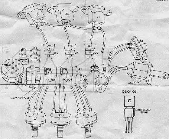
| Q3, Q4, Q5 | 3 | 106B1 SCR | Teccor S2003LS1 |
| T1 | 1 | 10K:600 Ohm Audio Transformer | |
| S1 | 1 | SPDT Switch | |
| J1, J2, J3 | 3 | AC Socket | |
| MISC | 1 | AC Line Cord, Crystal Microphone, Case, Wire |
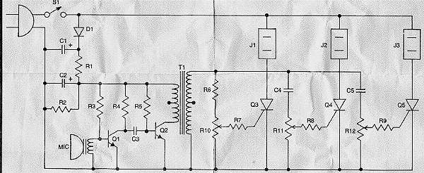
1. R10, R11 and R12 control the response of the different lights.
2. The circuit can handle up to 300 watts per channel.
3. This circuit is isolated from the 115 Volt line. If it is used with the case opened or not installed in a case, you could recieve a bad shock or be killed.
4. You can also use the Teccor S2003LS1 SCR for SCR1. These give better sensitivity and brightness than the 106B1 units.